Page 5 of 8
Re: Idle Issue/Ignition Timing Sensor
Posted: Jul Sun 13, 2014 6:19 pm
by benno3231

you have unearthed a demon!
Re: Idle Issue/Ignition Timing Sensor
Posted: Jul Sun 13, 2014 9:10 pm
by idubse7en
I know right
The wires on the right (there are 10 of them) were all soldered onto the single brown wire on the left (#35 on the ecu plug).
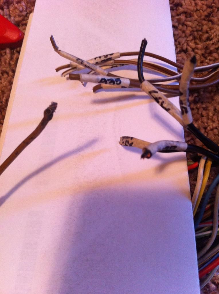
Can one of you guys tell me what that grey strip is (on the left side of the photo) were the wire terminate to?
My guess is an engine ground but i'm not sure.
Re: Idle Issue/Ignition Timing Sensor
Posted: Jul Mon 14, 2014 7:02 am
by MT-Getto
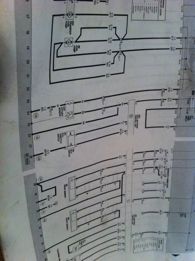
The circled number is a reference to ground location. Should say at beginning or end of section. And the left(bottom) is always ground on these "current flow" diagrams.
Re: Idle Issue/Ignition Timing Sensor
Posted: Jul Mon 14, 2014 9:58 pm
by idubse7en
Wow, the diagram is showing 10 wires that ground in motronic harness. So does that mean that the demon inside of mine is from the factory

I'm not sure what current flow is all about
Re: Idle Issue/Ignition Timing Sensor
Posted: Jul Tue 15, 2014 12:17 am
by benno3231
Current flow is basically where the wires connect and flow. Voltage drops as it hits each device, but current stays the same. And I'm on my way to an electrical engineering rant... anyways, don't over think it. Another human figured it out, you can too. Story of my life.
Re: Idle Issue/Ignition Timing Sensor
Posted: Jul Tue 15, 2014 5:37 am
by idubse7en
Eh, makes sense a little.
I am shopping for another engine harness for either parts or to replace this one.
Idle Issue/Ignition Timing Sensor
Posted: Jul Tue 15, 2014 7:09 am
by MT-Getto
You probably figured out that the top grey is the fuse box (built like a multilayer circuit board).
The first chapter in the electrical section usually has a decent explanation of reading these. I often refer back to it. The diagrams change slightly from Bentley to Bentley but are mostly the same.
Re: Idle Issue/Ignition Timing Sensor
Posted: Jul Tue 15, 2014 8:17 pm
by MT-Getto
idubse7en wrote:Look what I found under the edu connector boot wrapped in electrical tape, seven wires spiced into one brown wire

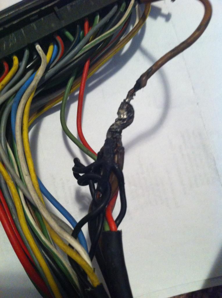
I hate to say........... but, the more I look at this, the more I think it may be a stock splice. Was there nice fuzzy coroplast tape on it?
Re: Idle Issue/Ignition Timing Sensor
Posted: Jul Wed 16, 2014 7:48 pm
by idubse7en
The splice was wrapped in a couple layers of electrical tape.
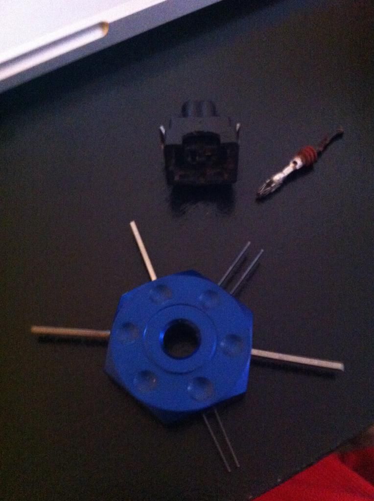
Got the terminal tool and it works with a little effort.
Re: Idle Issue/Ignition Timing Sensor
Posted: Jul Wed 16, 2014 10:34 pm
by SweaterVest
I had quite a few grounds like that in my vr6 harness. Wouldn't surprise me if that's stock