DIY: Audi A4 FMIC install
Posted: Aug Wed 26, 2009 4:56 pm
I picked up a FMIC pretty cheap and threw in on the other night, so I thought I would do a little DIY/writeup.
Tools needed:
Metric socket set w/ various extensions
10mm deep socket
Metric allen wrench w/ ball end
T25 and T45 Torx bits
Cordless drill
2x Hex screws for the boost sensor
2x Nylon lock nuts and bolts to secure the core tabs to the supplied mounting hardware
about 6 hours of time
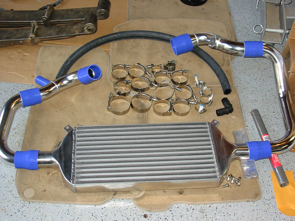
Here's the kit:
It comes with all the pipes and silicone connectors, wide clamps and the core. I planned on deleting the "cowbell" boost reservoir (explained later) so I picked up a few extra clamps and a 90 degree ABS plastic elbow which are shown below.
Pop the hood.

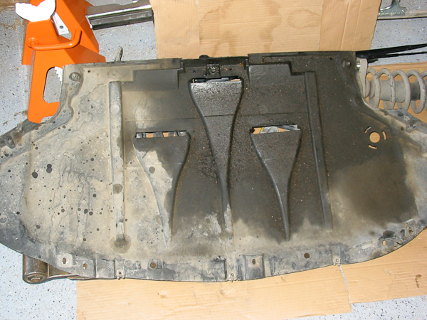
Remove the belly pan
Remove the snorkel and fog grilles

Here's the collection of parts so far:

Remove the headlights

Remove the 8mm bolt from under the bumper cover, which connects the bumper rebar to the bumper supports. Make sure all the various other bolts are removed from the the fender wells and the bumper should pull forward with some force.

Don't pull too hard because there are the headlight washer lines, homelink harness, fog light harness and in my case I also had fog ballast connectors to disonnect. Pull the washer fluid line off and plug the end of the washer line so you don't lose all your fluid.

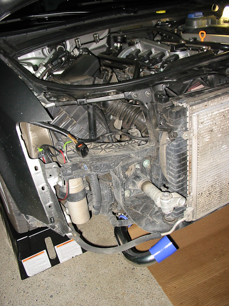
You should have a clear shot to your SMIC now

In order to get it out, it's required to pull the radiator core support forward a few inches. So remove the two bolts from the top of the core support/fender, and remove the driver side headlight plate by removing the three screws holding it in place

Two screws on the headlight plate

One screw holding the headlight plate to the fender

Use a T45 bit to unscrew the bumper support bolts about halfway - this will them allow you to pull the core support forward

Pull the core forward towards the front of the car

Now remove all the cold side hoses - the IC upper hose from the throttle body and make sure to remove the short 90 degree IC hose from the bottom of the SMIC. It's a little harder to remove, but just get western with it and it will come off.

Now pull forward on the top of the SMIC, and drop it down towards the ground and remove it

Now you should have an open space where the SMIC once sat

Remove the boost sensor and set it aside

Here's the collection of parts so far

Remove the air dams from around the radiator. There are three: one on the bottom and two on the side - remove the screws and set them aside

Time to move the power steering cooler - it needs to be rotated upward so the FMIC can sit flush.

I ended up having to trim out the part between the lines in the pic below with my dremel. This allowed me to swing the cooler up and out of the way

I secured the cooler with a couple of zip ties and screws the retainer bolt back down, and that cooler isn't going anywhere

Now I could work on removing the hot side IC hoses. Loosen the clamps on the turbo housing and the clamp on the other end, which secures the hose to the stock charge pipe

I chose to remove the "cowbell" boost reservior, so remove the 3 6mm bolts and remove the hose and clamp on the bottom of the DV and pull the entire assembly out

Now we should be done removing parts and can get on to installing the FMIC

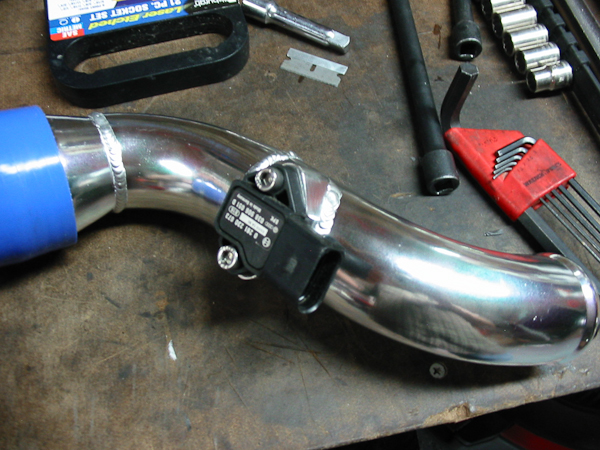
Time to install the boost sensor into the upper cold side pipe. I made a gasket from paper gasket material and then used a small amount of silicone sealant between the gasket and the bung

Carefully insert the sensor into the pipe - watch out so that the o-ring on the sensor does not get torn on the sharp edge of the bung. Use the two screws to secure the sensor

Mock up the boost tubes using the silicone hoses and clamps. Be sure to position the clamps so that they don't interfere with any other hoses or wires, and rotate them so it's easy to clamp them snug. I used my cordless drill with some attachments to secure the clamps. I used the torque setting on the drill so that I didn't over-tighten the clamps - but I made sure to get them nice and tight so I don't have any leaks.

On the hot side of the pipes, use the 90 degree fitting on the hose coming out of the upper pipe and attach it to the bottom of the DV, and secure all clamps.
After the pipes are mocked up, install the core following the same guidelines and making sure the pipes don't come into contact with anything.
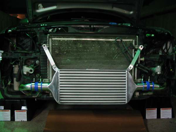
Make sure to hook up the boost sensor connector, and double check all your clamps and hoses, and you should be able to start the car and listen for leaks (if you have any). Be aware that you may need to clear codes for anything that's not hooked up - i.e. headlights or fog lights etc.
After everything checks out, the bumper can be reinstalled and everything else reconnected in reverse of how you removed it.
I didn't need to trim anything on the bumper, but I did need to trim a tab and the back of the fins on the fog light grills.
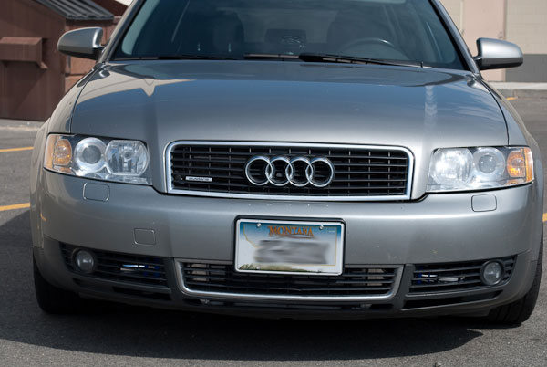
Here's the finished product:
Tools needed:
Metric socket set w/ various extensions
10mm deep socket
Metric allen wrench w/ ball end
T25 and T45 Torx bits
Cordless drill
2x Hex screws for the boost sensor
2x Nylon lock nuts and bolts to secure the core tabs to the supplied mounting hardware
about 6 hours of time
Here's the kit:
It comes with all the pipes and silicone connectors, wide clamps and the core. I planned on deleting the "cowbell" boost reservoir (explained later) so I picked up a few extra clamps and a 90 degree ABS plastic elbow which are shown below.
Pop the hood.
Remove the belly pan
Remove the snorkel and fog grilles
Here's the collection of parts so far:
Remove the headlights
Remove the 8mm bolt from under the bumper cover, which connects the bumper rebar to the bumper supports. Make sure all the various other bolts are removed from the the fender wells and the bumper should pull forward with some force.
Don't pull too hard because there are the headlight washer lines, homelink harness, fog light harness and in my case I also had fog ballast connectors to disonnect. Pull the washer fluid line off and plug the end of the washer line so you don't lose all your fluid.
You should have a clear shot to your SMIC now
In order to get it out, it's required to pull the radiator core support forward a few inches. So remove the two bolts from the top of the core support/fender, and remove the driver side headlight plate by removing the three screws holding it in place
Two screws on the headlight plate
One screw holding the headlight plate to the fender
Use a T45 bit to unscrew the bumper support bolts about halfway - this will them allow you to pull the core support forward
Pull the core forward towards the front of the car
Now remove all the cold side hoses - the IC upper hose from the throttle body and make sure to remove the short 90 degree IC hose from the bottom of the SMIC. It's a little harder to remove, but just get western with it and it will come off.
Now pull forward on the top of the SMIC, and drop it down towards the ground and remove it
Now you should have an open space where the SMIC once sat
Remove the boost sensor and set it aside
Here's the collection of parts so far
Remove the air dams from around the radiator. There are three: one on the bottom and two on the side - remove the screws and set them aside
Time to move the power steering cooler - it needs to be rotated upward so the FMIC can sit flush.
I ended up having to trim out the part between the lines in the pic below with my dremel. This allowed me to swing the cooler up and out of the way
I secured the cooler with a couple of zip ties and screws the retainer bolt back down, and that cooler isn't going anywhere
Now I could work on removing the hot side IC hoses. Loosen the clamps on the turbo housing and the clamp on the other end, which secures the hose to the stock charge pipe
I chose to remove the "cowbell" boost reservior, so remove the 3 6mm bolts and remove the hose and clamp on the bottom of the DV and pull the entire assembly out
Now we should be done removing parts and can get on to installing the FMIC
Time to install the boost sensor into the upper cold side pipe. I made a gasket from paper gasket material and then used a small amount of silicone sealant between the gasket and the bung
Carefully insert the sensor into the pipe - watch out so that the o-ring on the sensor does not get torn on the sharp edge of the bung. Use the two screws to secure the sensor
Mock up the boost tubes using the silicone hoses and clamps. Be sure to position the clamps so that they don't interfere with any other hoses or wires, and rotate them so it's easy to clamp them snug. I used my cordless drill with some attachments to secure the clamps. I used the torque setting on the drill so that I didn't over-tighten the clamps - but I made sure to get them nice and tight so I don't have any leaks.
On the hot side of the pipes, use the 90 degree fitting on the hose coming out of the upper pipe and attach it to the bottom of the DV, and secure all clamps.
After the pipes are mocked up, install the core following the same guidelines and making sure the pipes don't come into contact with anything.
Make sure to hook up the boost sensor connector, and double check all your clamps and hoses, and you should be able to start the car and listen for leaks (if you have any). Be aware that you may need to clear codes for anything that's not hooked up - i.e. headlights or fog lights etc.
After everything checks out, the bumper can be reinstalled and everything else reconnected in reverse of how you removed it.
I didn't need to trim anything on the bumper, but I did need to trim a tab and the back of the fins on the fog light grills.
Here's the finished product: